Search Results for: STM32

USB bootloaders for AVR microcontrollers

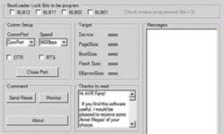
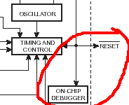
Probably the most proper microcontroller programming method is using a bootloader program. Because you don’t need any special programming adapters or special knowledge – you need to connect a standard cable from your PC to the target board and run a special program on the PC which communicates with the MCU bootloader program. The idea is simple: If the microcontroller is preconfigured, then after reset, it starts running not from the start memory location, which is usually at 0x0000 address, but at some specific location, where usually bootloader lies.

Continue reading

Robotic Assistance for the Disabled

Embedded devices, particularly digital ones specially designed to assist individuals with disabilities, are often seen as the next step in that particular field of technology.  Such embedded devices generally have several advantages over the previous wave of embedded devices that have monitoring functions, control capabilities, and the ability to access and use communication protocols like the internet.  The modern embedded applications devices do not stop monitoring, tracking, and relaying information; they almost always directly assist the user, such as a prosthetic limb or a personal transport assistance vehicle.

Continue reading

How to describe embedded software design using diagrams and pseudo-code

When designing embedded hardware, you probably want to visually express what embedded software will be performing and how different functions depend on each other. How to make software documentation simple, clear, and informative. If you are a developer, you may want to explain your ideas understandably without loads of code text. Depending on what level of information has to be provided, you may choose any of the following. Data Flow Diagram Data flow diagrams are used to see the processes and what data is transferred between different functions. This way, each process or function is expressed as a block (or any other shape), while lines show what information passes between processes. As you can see in the example figure simple data flow diagram is presented. Without program code, it is easy to read how the program operates:

Continue reading

DIY USB to RS232 adapter

Sometimes you need to connect some device to a COM port, but the computer doesn’t have one, especially a laptop. There are two ways – go and buy a USB to COM adapter or build one. So if you decided to build a USB to COM(RS232) adapter, there is one solution. This adapter is straightforward to build as there is a single-chip USB to UART bridge (CP2102). This chip from Silicon Labs supports USB2.0 full speed. Internal Resistors are required for the USB interface, integrated clock, internal 1024 -byte EEPROM for Vendor ID, Product ID serial number, power descriptor, and other information. SP2102 USART part support almost all standard features of RS232 communication including handshaking, Databits (5, 6, 7, and 8); 1 or 2 stop bits; odd, even, mark, space, and no parities; baud rate from 300bps to 1Mbits.

Continue reading

What is worst-case timing analysis

Many of your PC hardware people have probably faced similar problems when assembling a computer from different parts, and it seemed to work properly. But under some circumstances system crashes without any known reason. Even in my practice, I had a sound-card that works well, but time at the time, it just crashes, and then the computer hangs. Of course, I can blame drivers or operating systems, but there is another probability that there can some timing failures occur. Many complex productions around us may have many undefined failures due to a lack of timing worst-case analysis. Failures may occur due to power supply fluctuations, thermal changes, or other conditions. Worst-case analysis encounters all available information of condition variations that can affect the performance of components. The worst-case analysis shows if electronic design meets specifications under variable conditions like temperature, voltage, or other variables. Only detailed analysis can prove if the design will work reliably under all operating conditions. It is proved that it is much better to design reliable hardware than fix the problems later. In many ways, the worst-case analysis may be implemented in various manufacturing phases automatically. By including several simple tests may save lots of money…

Continue reading

JTAG wiggler clone for ARM microcontrollers

The Olimex ARM JTAG clone is well known as there are many schematics on the internet available. Circuits are straightforward and seem to be reliable. This adapter can also be set up to work with WinARM tools: obdremote and gdb/Insight-gdb. In the circuit, there is a critical part that needs to be considered – 74HC244 buffer IC. Family of HC support less than 4.8V if powered with 3.3V. But reality shows that Parallel port voltage usually is lower than 5V so that HC will fit. But of course, it is better to measure the HIGH state of parallel port pins. To be more sure, HC should be replaced by 74LVP244 or 74LPT244. These chips support 5.5V in entry with a 3.3V supply, but sometimes they are hard to find in the market.

Continue reading

Interrupt system of ARM LPC2000 microcontrollers

Microcontrollers aren’t imaginable without interrupts. The arm isn’t an exception. There were SWI exceptions mentioned in earlier articles, but there are two more sources of exceptions: IRQ(General Purpose Interrupt) and FIQ(Fast Interrupt). ARM Pin Connect Block All I/O pins of LPC2000 ARM can be multiplexed to several functions via pin select block. Pin selection bloc allows selections up to three more other functions except for GPIO. Pin Connect block gives flexibility to ARM MCU because each PIN can have different functionality. After reset, all pins are configured as GPIO. As the example above, you can see that the P.1 pin function can be assigned by PINSEL0 register 3 and 2-bit configurations. So if you write PINSEL0|=(1<<3)|(1<<2), then the pin will be assigned to the EINT0 function. Pretty simple. So before using External interrupt EINT0, first, you have to select the pin function for the P0.1 pin.

Continue reading

Debugging embedded hardware and software traces

When designing an embedded project, we typically focus on the actual application but do not pay enough attention to the hardware and software debugging process. Adding the debugging capability to the project requires some strategy. Simple situation: hardware may not be installed but connected to another circuit when needed. So software must support the functionality regardless of whether or not hardware is installed. Another example may be Embedded inboard with multiple temperature sensors. Hardware should detect when the sensor is connected or disconnected without interrupt other sensors’ readings. One way of debugging is software trace(log) to provide historical information on what was happening if something went wrong. This technique is a good solution for developers who have no ability to use other debugging tools because of the following reasons:

Continue reading

Debugging tools for ARM7

Usually, one solution of debugging is to run compiled code on a PC simulator. You can download a limited version of the instruction set simulator from Hitex for free. Of course, better simulators aren’t for free. More advanced simulators you can purchase at Keil. More advanced, I mean that there is the ability to simulate peripherals by additional scripting and so on. But again, simulators are virtual tools, and usually, it is hard to simulate real-world events. Once you face this problem, you are going to switch to real-world simulation using JTAG.

Continue reading

Function calls and stacking of parameters in embedded systems

Usually, when you write C programs for microcontrollers, you use functions that can be called any time in the main program or another function. The compiler compiles these functions as subroutines. These functions can be called from the main function or other functions – this is called nesting (nested subroutines). If you see the compiled program’s listings, you will see that subroutines are called by using the call or rcall keyword. The argument of this instruction is a subroutine address that will be executed on the next processor cycle. Call instruction also writes return address from function to the stack to continue the program after returning from the function.

Continue reading